If you’ve ever stood beside a winding machine in a transformer or electric motor workshop, you’ve probably reached for an enameled flat wire without thinking twice. But if you’re like the engineers and technicians who knock on my door every week, you’ve also stared at a schematic or a motor design file and wondered, “What’s the actual capacitance here?” It’s not the most glamorous part of building power equipment, but get that number wrong and you’re looking at anything from a transformer that hums too loud to a motor that wastes 10% more energy than it should. Let me walk you through this—straight from the shop floor of the Enameled Flat Wire supplier I run, no stuffy textbook jargon that doesn’t apply to the parts you actually use. Enameled Flat Wire
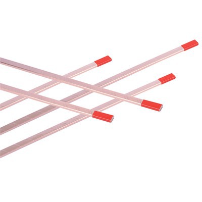
First, let’s get one thing straight: when we talk about capacitance in enameled flat wire, we’re not talking about a standalone capacitor you’d pick up at an electronics store. This is parasitic capacitance—the tiny, unwanted electrical charge that builds up between adjacent strands, between layers of winding, or even between the wire and the core it’s wrapped around. For round magnet wire, this number is relatively straightforward, but flat wire changes everything. Flat wire has more surface area touching its neighbor, right? That means more space for that charge to build, which is a big deal for high-frequency applications, high-voltage transformers, or small, dense motors.
Let’s break down the basics of how this works. Capacitance, at its core, is a measurement of a component’s ability to store an electrical charge. The formula you’ll see in every engineering textbook is C = ε * A / d, where ε is the permittivity of the insulating material (in our case, that’s the enamel coating), A is the overlapping area between two conductors, and d is the distance between those conductors. For enameled flat wire, the “conductors” here are the bare copper or aluminum wires, and the “insulator” is the thin layer of baked-on enamel that coats every inch of the wire. Round wire twists and turns as it’s wound, so the overlapping area between two adjacent turns is small and inconsistent. But flat wire? When you wind a flat wire in a layer, each next turn sits flush against the one before it, with almost the entire width of the wire touching. That means A is way bigger, which makes capacitance higher—sometimes two to three times higher than a round wire of the same cross-sectional area.
But here’s where the real story begins, because not all enamel is made equal, and not all flat wire is the same. Let’s start with the wire itself. The dimensions of the flat wire matter more than you might think. If you have a 0.1mm thick, 2mm wide flat wire versus a 0.2mm thick, 4mm wide wire, even if the copper area is the same, the capacitance will differ. Wait—why? Because the distance d between two layers isn’t just the enamel thickness. If you have a thinner enamel coating, d is smaller, so C goes up. But if your wire is thicker, the distance between the top of one layer and the bottom of the next is the sum of two enamel layers plus two wire thicknesses. That d number is critical. I’ve had a customer who switched from 0.15mm thick flat wire to 0.2mm thick for a high-frequency induction heater project, and his capacitance jumped by 18%—enough to throw his whole circuit off balance. That’s the kind of thing you learn from sitting across the table from a designer who just had to rewind 50 transformers because they didn’t account for that variable.
Next, the enamel coating. As a flat wire supplier, we use three main types of enamel for our products, each with a different permittivity, which directly changes capacitance. Standard polyester enamel is the most common, with a permittivity (let’s call it ε_r for relative permittivity, since that’s what engineers actually use) of around 3.5. For high-voltage applications, we use polyurethane enamel, which has an ε_r of about 4.8. Then there’s the premium polyimide enamel for extreme heat, with an ε_r of 3.2. That’s a big spread, right? If you use polyurethane instead of polyimide, your capacitance is 50% higher for the same wire dimensions and winding setup. A lot of customers don’t realize that switching enamel isn’t just about heat resistance—it’s a direct tuning point for parasitic capacitance. Last year, a motor manufacturer came to us because their prototype was failing EMC (electromagnetic compatibility) tests. They’d been using standard polyester enamel, but their high-speed motor had too much common-mode noise from that high capacitance. We switched them to polyimide enamel, and their capacitance dropped enough to get them through testing on the first try. No rewinding, no lost time—just a choice of material that makes all the difference.
Then there’s how you wind the wire. Capacitance isn’t just about the wire itself—it’s about how it’s arranged. If you wind your flat wire tight, with no gaps between turns, the overlapping area A is maximum, so capacitance goes up. Leave a small gap between turns, and A shrinks, so C goes down. For multi-layer windings, the way you cross from one layer to the next matters too. If you wind each layer in the same direction, you’ll have higher capacitance between layers than if you alternate layers direction. I always tell customers: if your design is struggling with too much capacitance, the first thing to check isn’t the wire—it’s your winding tension and pattern. We’ve got a case study from a medical device client who was designing a high-frequency pulse transformer for a defibrillator. They’d been winding with a standard 10mm gap between turns, giving them a capacitance of 1200 pF. When they reduced the gap to 2mm to save space, their capacitance jumped to 3800 pF—enough to make the transformer’s timing off by 2 microseconds, which is a dangerous error in a medical device. We worked with their engineering team to adjust the gap, and they found a middle ground that kept the size small and capacitance within their specs.
Now, let’s get to the part that always confuses people: how do you actually measure this capacitance, because it’s not a simple number. The textbook formula gives you a rough estimate, but real-world conditions change it. For example, when you wind a flat wire into a coil, the capacitance between turns and layers isn’t just parallel—it adds up in different ways, and you also have capacitance between the coil and the metal core or the casing around it. That parasitic capacitance from the core depends on how close the coil is to the core material, which is a variable in your design, not just the wire. A lot of new engineers will plug the formula into a calculator and get a number, but then build a prototype and find it’s 30% off. Why? Because they forgot about the core capacitance, or the way the wire bends during winding changes the overlapping area slightly, or even the temperature—enamel permittivity changes a little with heat, so capacitance goes up as your device runs.
As an enameled flat wire supplier, we’ve developed a few ways to help our customers get the right capacitance without guessing. First, we test every batch of our wire to get exact dielectric thickness and enamel type data, so we can plug those numbers into the capacitance formula with precise values, not generic ones. Second, we offer custom enamel coatings—we can adjust the thickness of the enamel on the flat wire’s wide face (the part that touches adjacent turns) or the narrow face (the part that touches layers) to tweak capacitance. Wait, right! Most flat wire has a different enamel thickness on the wide side than the narrow side, because the wide side gets more wear during winding. If you need lower capacitance, you can make the enamel on the wide side (where overlapping happens) thinner, or if you need higher capacitance, you can make it thicker? No, wait—thinner enamel means lower d, so higher C. Thicker enamel means higher d, lower C. That’s a custom tweak we do all the time for customers with very specific needs. We had an aerospace client last year working on a satellite power converter; they needed a very specific capacitance of 550 pF per meter of wire. Off-the-shelf wire was giving them 720 pF, so we adjusted the enamel thickness on the wide face of the flat wire, and got them exactly the number they needed on the first run.
I also need to talk about common mistakes I see customers make all the time. First, confusing DC capacitance with AC capacitance. The formula I mentioned earlier is for DC, but when you’re dealing with high-frequency AC (which is common in motors, transformers, and power electronics), the capacitance is slightly different. The alternating current changes the way the charge builds up, so at high frequencies, parasitic capacitance has an even bigger impact. Second, not accounting for the conductor material. Copper and aluminum have almost the same impact on capacitance, right? Because the permittivity is all about the enamel, not the wire. But wait—no, the conductivity of the wire affects how the charge distributes, so for very high-frequency applications, the type of conductor can have a tiny impact, but that’s negligible for most designs. The bigger mistake is using a round wire calculator for flat wire capacitance. I’ve seen so many designs where engineers plug in round wire numbers and get a way too low or way too high capacitance, leading to prototype failures.
Another thing to consider: when we talk about enameled flat wire, sometimes we’re referring to litz flat wire, which is made of many fine insulated strands bundled flat. That adds another layer of complexity to capacitance, because now you have capacitance between the fine strands inside the litz wire, plus capacitance between the litz bundle and adjacent turns. Litz wire is often used for high-frequency applications to reduce skin effect, but its capacitance is higher than solid flat wire of the same total cross-sectional area, because of all those small insulation layers between the strands. That’s a trade-off customers have to make: lower AC loss with litz wire, but higher capacitance. As a supplier, we can adjust the insulation thickness of the individual litz strands to balance that, but it’s a detail that’s easy to overlook.
Let’s wrap this up with a practical example, because numbers make this real. Suppose you have a standard 0.1mm thick, 1mm wide solid enameled flat wire with polyimide enamel (ε_r = 3.2) and an enamel thickness of 0.02mm on each face. The overlapping area between two adjacent turns is 1mm * 1mm = 1 mm², and the distance between the two conductors is 0.02mm + 0.02mm = 0.04mm. Plugging into the formula: C = (8.854 x 10^-12 F/m * 3.2) * (1 x 10^-6 m²) / (0.04 x 10^-3 m) = ~710 pF per meter. Now, if that same wire was polyurethane enamel (ε_r = 4.8), that number jumps to ~1070 pF per meter. If you increase the enamel thickness to 0.03mm, d becomes 0.06mm, so C drops to ~470 pF per meter. That’s the kind of range you’re working with, and it’s all within the same wire dimensions—just material and thickness changes.
At the end of the day, the “capacitance of enameled flat wire” isn’t a single number you can look up. It’s a value that depends on wire dimensions, enamel type and thickness, winding pattern, application frequency, and even the materials around the wire. The best way to get the right number for your project is to work with a supplier who understands this, not just sells wire off a shelf. As someone who’s been in this business for 15 years, I’ve seen hundreds of projects go sideways because someone guessed at capacitance instead of asking for specific data.
If you’re working on a new motor, transformer, power converter, or any project where parasitic capacitance matters, don’t waste time with generic estimates. Reach out to our team to talk through your requirements—we’ll help you calculate the exact capacitance you need, adjust the wire dimensions and enamel specs to hit that number, and make sure your prototype works on the first try. We don’t do one-size-fits-all here, and we’re not just selling wire—we’re solving problems with you.
Continuously Transposed Conductors References
- Electrical Insulation for Rotating Machines: Design, Evaluation, Aging, Testing, and Repair, 2nd Edition, IEEE Press, 2011.
- Handbook of Transformer Design and Applications, 3rd Edition, McGraw-Hill, 2013.
- Litz Wire and High-Frequency Application Design Guide, Elektronik Publishing, 2020.
- Dielectric Materials for Electrical and Electronic Insulation, 2nd Edition, Wiley-IEEE Press, 2018.
Tianjin Jingwei Power Technology Co., Ltd.
As one of the most professional enameled flat wire manufacturers and suppliers in China, we’re featured by quality products and good service. Please rest assured to buy durable enameled flat wire made in China here from our factory. Contact us for more details.
Address: No.1 Chuangxin Rd. Xiaozhan Industrial Park, Jinnan District, Tianjin, China
E-mail: info@jwdc.cn
WebSite: https://www.jw-dcs.com/
